How to Choose Barite Drywall for Radiation Shielding

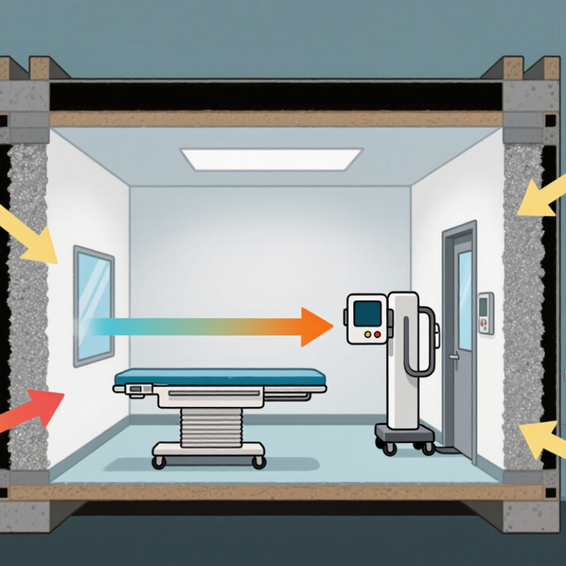
Choosing Barite Drywall Radiation Shielding begins with understanding the room, not simply selecting the heaviest panel. Barite drywall uses barium sulfate to increase density and reduce scattered radiation. Its effectiveness depends on thickness, material density, joint treatment, and installation quality. A poorly sealed penetration can weaken an otherwise careful design. Small gaps matter.

Medical physicist Dr. John R. Cameron offered a useful radiation-safety principle: “Radiation is not dangerous if it is properly controlled.” That idea still applies here. Proper control requires a qualified shielding assessment, based on the equipment’s workload, operating voltage, beam direction, room occupancy, and adjacent spaces. A dental imaging room may need a different solution from a high-use diagnostic radiography room. The answer is never universal.

Look for products with verified density, consistent thickness, clear technical data, and dependable fire-performance information. Ask whether the manufacturer provides installation guidance for seams, corners, outlets, doors, and service openings. These details are easy to overlook. Do not rely on visual weight alone. A dense board may still fail when installers leave unprotected joints or compressible gaps.

There is also a practical limitation. Barite drywall can reduce radiation exposure, but it cannot replace professional calculations, compliance checks, or commissioning measurements. I may sound overly cautious, yet shielding mistakes are difficult to notice after the walls are closed. The safest choice combines tested material, competent design, skilled installation, and documented verification. That is where Barite Drywall Radiation Shielding becomes a controlled engineering decision, rather than a guess based on product appearance.
How to Choose Barite Drywall for Radiation Shielding

What Barite Drywall Is and How It Provides Radiation Shielding

Barite drywall is a gypsum panel containing barite, a dense mineral made mainly of barium sulfate. Its higher density can reduce the transmission of diagnostic X-rays and some gamma radiation. The barite does not “absorb everything.” Performance depends on photon energy, panel thickness, joints, and installation quality.

NIST’s XCOM database provides mass attenuation data across different photon energies, but it does not certify one universal barite drywall thickness. That distinction matters. NCRP Report No. 147 recommends evaluating workload, distance, occupancy, and use when designing medical X-ray barriers. Its commonly applied design goals are 0.1 mGy per week for controlled areas and 0.02 mGy per week for uncontrolled areas. These figures guide design. They do not replace a site calculation.

In practice, select panels using verified density, lead-equivalent or attenuation data, and tested assembly details. A small open joint can weaken an otherwise heavy barrier. Electrical boxes and pipe penetrations also need attention. I would not choose a panel from thickness alone. Barite density varies between products, and published values may reflect laboratory samples rather than installed walls. A qualified medical physicist should check the room layout, equipment workload, and local requirements before purchase. The imperfect part is often installation, not the mineral itself.


How to Choose Barite Drywall for Radiation Shielding

Barite drywall uses high-density barium sulfate to increase shielding mass within a wall system. The chart compares representative material-density ranges; higher density can improve photon attenuation per unit thickness, but final shielding performance also depends on radiation energy, wall thickness, joints, and construction details.

Key point: Barite drywall is substantially denser than standard gypsum board while remaining less dense than lead. Select the required panel thickness and system design using the applicable shielding calculation, local regulations, and verified product data.

Radiation Protection Needs in Different Building Environments

How to Choose Barite Drywall for Radiation Shielding

Radiation protection needs change sharply between building environments. A dental imaging room may have brief exposures, while a CT suite handles repeated high-output scans. NCRP Report No. 160 estimated medical sources represented 48% of average U.S. radiation exposure in 2006. That figure explains why shielding decisions deserve more than a material comparison.

Barite drywall contains dense barium sulfate, helping reduce scattered X-rays when installed as part of a designed barrier. However, thickness should follow the room’s workload, tube voltage, distance, and occupancy. An occupied office behind the wall needs more attention than an empty storage area. The IAEA’s Safety Reports Series No. 47 recommends evaluating primary and secondary barriers separately. Door frames, joints, service penetrations, and ceiling connections can undermine an otherwise thick wall.

In hospitals, examine CT rooms, radiography rooms, and procedure spaces differently. CT shielding often depends on workload and the surrounding floor plan, not only the scanner’s rating. In dental clinics, adjacent corridors and waiting areas may still require careful assessment. Use current equipment data and a qualified medical physicist’s calculations. Old room assumptions can fail.

Measure carefully.

Barite drywall is not automatically safer than every alternative. Poor installation leaves weak points, and published data may not match local construction. IAEA guidance also stresses verification after installation. A site survey, documented barrier schedule, and radiation measurements provide stronger evidence than product thickness alone. Some uncertainty remains, especially when future workloads are guessed. That deserves honest review.

Key Factors for Choosing Barite Drywall Thickness and Density

Choosing barite drywall starts with a radiation survey, not a preferred board size. A qualified medical physicist should review workload, tube voltage, distance, and room occupancy. These values determine the required shielding design. Thickness is only one part.

At the same thickness, denser material usually provides greater attenuation. However, density ratings can differ between suppliers and tested assemblies. Request the declared density, thickness tolerance, and performance data for the actual system. Do not estimate protection from board weight alone. That shortcut is tempting, but unreliable. The design should identify the required barite-equivalent or lead-equivalent protection for each barrier.

Ceilings, floors, door frames, service penetrations, and joints need the same attention as the main wall. Staggered seams can reduce direct gaps. Fasteners should not create open channels through the barrier. During installation, inspect every joint before closing the second layer. On site, a narrow unsealed gap can matter more than a small thickness difference. That detail is easy to miss. Construction changes happen. If equipment settings or room use changes, recalculate the shielding instead of adding material casually. Independent inspection and documented measurements provide stronger evidence than assumptions.

How to Choose Barite Drywall for Radiation Shielding - Key Factors for Choosing Barite Drywall Thickness and Density

Design Factor Typical or Reference Values Why It Matters Selection Guidance
Radiation type Diagnostic X-rays, gamma rays, and high-energy photons require different shielding calculations. Attenuation depends on photon energy, workload, distance, and occupancy. Identify the equipment maximum operating voltage or photon energy before selecting thickness. Do not size the wall from material density alone.
Barite drywall density Common heavy-board range: approximately 2.0–2.4 g/cm³ (2,000–2,400 kg/m³), subject to the product specification. Higher density generally provides greater attenuation per unit thickness, but density is not a substitute for a radiation shielding calculation. Use the tested or certified density stated for the selected board. Verify that the density is uniform throughout the panel.
Board thickness Common nominal thicknesses include 12.5 mm, 15 mm, 19 mm, and 25 mm. Increasing thickness increases the radiation path length and total shielding mass. Choose the thinnest tested configuration that meets the calculated design requirement, then consider additional layers where necessary.
Area density Approximate area density equals thickness × material density. Area density helps compare shielding layers and estimate wall loading. Check the supporting structure, framing, floor loading, and fastening system before installation.
Number of layers One or more layers may be used depending on the calculated shielding requirement. Multiple layers can increase total thickness and allow joints to be staggered. Stagger vertical and horizontal joints between layers. Treat the complete assembly—not an individual panel—as the shielding system.
Joints and seams Joints should not create a direct radiation path or reduce the specified shielding thickness. Small gaps, poorly aligned joints, and unshielded penetrations can become weak points. Use compatible heavy shielding joint treatment and maintain continuous coverage at corners, junctions, and wall-to-ceiling connections.
Penetrations and openings Electrical boxes, ducts, pipes, cable trays, doors, and windows require separate shielding details. Openings can reduce effective shielding even when the surrounding wall has adequate thickness. Coordinate penetrations with the shielding design and use overlapping or locally reinforced details where required.
Workload and use factor The calculation should consider weekly workload, beam direction, occupancy, and distance to occupied areas. A frequently used room or an occupied area immediately behind the barrier may require more shielding. Provide the shielding designer with equipment workload, room layout, adjacent occupancy, and expected operating schedule.
Structural and installation requirements Heavy boards can weigh substantially more than ordinary gypsum panels. Excessive weight can affect studs, anchors, ceilings, floors, handling, and installation safety. Confirm framing capacity, fastener spacing, panel handling limits, and fire or moisture requirements before construction.
Verification and compliance Shielding should be designed and reviewed using applicable local regulations and recognized radiation-protection guidance. Material datasheets alone generally do not establish compliance for a complete room. Have the final design reviewed by a qualified medical or radiation-shielding physicist and verify the installed room where required.

Approximate Area Density by Board Thickness

Nominal Board Thickness Area Density at 2.0 g/cm³ Area Density at 2.2 g/cm³ Area Density at 2.4 g/cm³ Practical Note
12.5 mm 25.0 kg/m² 27.5 kg/m² 30.0 kg/m² Suitable only when the calculated shielding requirement is met by a single layer or when used as part of a multilayer system.
15 mm 30.0 kg/m² 33.0 kg/m² 36.0 kg/m² Check framing and fasteners because the mass is considerably higher than standard gypsum board.
19 mm 38.0 kg/m² 41.8 kg/m² 45.6 kg/m² Often considered where greater shielding per layer or increased durability is required, subject to tested system details.
25 mm 50.0 kg/m² 55.0 kg/m² 60.0 kg/m² Requires careful structural review and installation planning because of the high mass per unit area.

Calculation basis: Area density = board thickness in metres × material density in kg/m³. The values above are approximate and are not a substitute for a project-specific radiation-shielding calculation. Actual performance depends on radiation energy, board composition, joints, penetrations, installation quality, and the complete wall assembly.

How to Compare Product Quality, Safety Standards, and Installation Methods

How to Choose Barite Drywall for Radiation Shielding

Product quality starts with measured density, not appearance. Ask for batch test results, panel thickness, moisture content, and declared radiation attenuation. Barite distribution should remain uniform across the board. A heavy corner does not prove reliable shielding. NCRP Report No. 147 explains that shielding design depends on workload, beam energy, distance, use factor, and occupancy. Therefore, a fixed “lead-equivalent” claim needs project-specific verification. IAEA Safety Reports Series No. 47 also supports calculations by a qualified medical physicist.

Safety documents should be checked before installation. Request independent laboratory reports, material safety data, fire-performance results, and quality-control records. ASTM C1396 covers gypsum panel requirements, while ASTM C840 addresses gypsum panel installation practices. These standards do not replace radiation calculations. That distinction is often missed. A panel may meet general construction requirements but still fail at joints or service penetrations. Compare test conditions carefully, including radiation energy and panel configuration.

Installation quality is equally important. Stagger board joints, seal gaps, and maintain the specified overlap around doors, outlets, ducts, and pipe sleeves. One visible crack can reveal a wider coordination problem. Use compatible fasteners and avoid crushing panel edges during lifting. I have seen drawings specify adequate thickness while installers overlooked a small cable opening. That mistake is not dramatic during construction, but it can weaken the shielding path. Photograph each concealed layer, record batch numbers, and arrange a final survey with calibrated equipment. A second review is worthwhile; assumptions are where shielding projects become fragile.

How to Plan, Install, and Inspect a Barite Drywall Shielding System

How to Choose Barite Drywall for Radiation Shielding

Planning starts with the radiation source, not the wall panel. Record workload, beam direction, room occupancy, distances, and adjacent spaces. NCRP Report No. 147 states that these factors control medical imaging shielding design. IAEA Safety Reports Series No. 47 also emphasizes workload, occupancy, and distance. Barite drywall density can vary, so request verified density and attenuation data for the exact panel thickness. A generic “radiation-resistant” claim is not enough.

Mark every joint, corner, doorway, ceiling connection, and service penetration before installation. Stagger panel seams between layers, close gaps tightly, and use compatible reinforcement around outlets and pipes. Small openings can weaken an otherwise substantial barrier. They are easy to overlook. Do not assume extra thickness fixes poor workmanship.

Inspect the finished system with drawings, delivery records, and photographs. Check panel labels, fastener spacing, joint offsets, and sealed penetrations. A qualified radiation protection physicist should perform a post-installation survey under representative operating conditions. Compare measured results with the approved design limits and document each location. NCRP Report No. 147 recommends verification through radiation surveys and quality assurance procedures. The honest weakness is often the inspection plan: if nobody records hidden joints before closing the wall, later verification becomes partly guesswork. Recheck after equipment changes or room renovation.

Get a Quote
910-483-7828